|
Device Fabrication and Design Guidelines
It is impossible to describe the design methodology behind every single device designed so far for the isolation of single cells. However, most chips revolve around a few general parameters, summarized below.
Materials Selection
Materials selection is an important first step in the design of any device. In the case of microfluidics for clinical analysis, poly(dimethylsiloxane), or PDMS for short, has become the gold standard.
The reasons for this are many:
- Cost: Cheap and thus ideal for the large-scale manufacture of single-use assays.
- Mechanical properties: Rugged and rigid yet flexible polymer that can survive the rigors of a lab. Despite this, can reproduce channels down to twenty microns.
- Optical properties: Transparent for visible and UV wavelengths, allowing for optical as well as fluorescent assays.
-
Chemical properties: Nontoxic to cells, can form reversible or irreversible seals during manufacture and use. Additionally, features a hydrophilic surface which easily facilitates the flow of water through etched microchannels. Surface can be made hydrophobic if needed in a simple process such as silanization.
| 
PDMS, the most common material for microfluidic device fabrication.
|
Photo/Soft Lithography
Lithography, a concept from the semiconductor industry, is the primary means of patterning a polymeric surface. The two-step process is as follows:
Photolithography for fabrication of master:
|
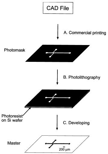
The general process for photolithography, nearly identical to its cousin in the semiconductor industry.
|
Soft Lithography for fabrication of device:
- Apply 10:1 ratio of PDMS + binding agent to master
- Cure at 80 degrees Celsius for one hour
- Mechanically separate device from master
-
Apply pumps, glass coverslips, etc. as necessary. Details such as surface modifications can be applied now also. All such structures are designed to facilitate the manipulation of reagents, biomarkers, etc.
|
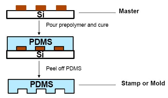
The general process for soft lithography.
|
Microfluidic-basded Devices Engineered for Isolating Cells:
Static vs. Hydrodynamic Approaches
| Large-Scale Single-cell Trapping Microarray by Folch Lab (PI: Professor Albert Folch) |
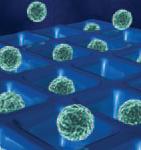
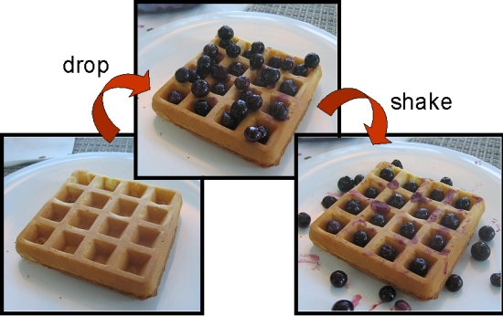
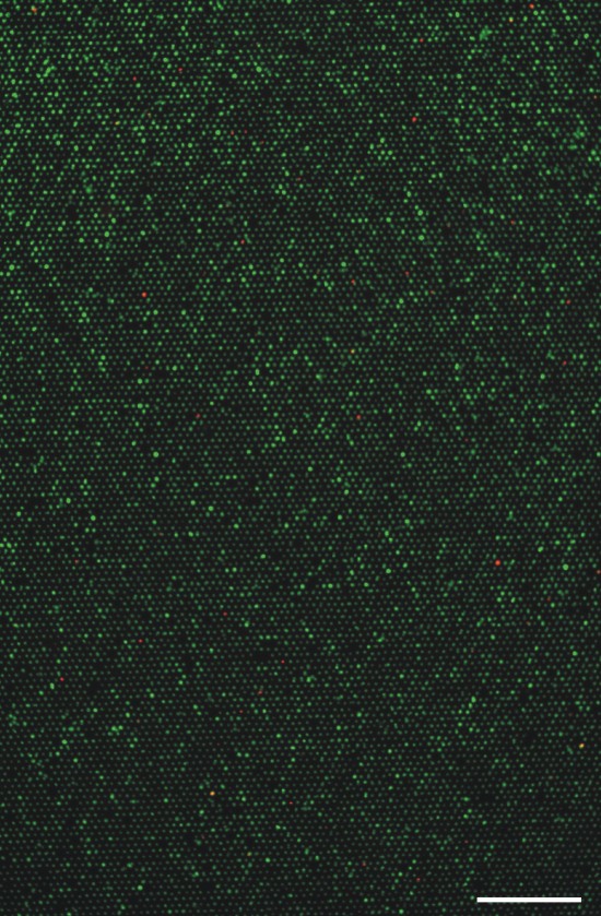
Albert Folch’s simple idea made its way onto the cover of Lab-on-a-Chip. It can be best explained as an ice cube tray (or a waffle, as depicted below), with each well sized to hold a specific number of cells. The cells wander into wells and become trapped and immune to the fluid flow above. Leftover cells that cannot find an empty well are perfused away from the device. Such a device can be easily scaled up: Folch Lab has fabricated an example with over twelve thousand wells, as depicted. However, it can be difficult to uniformly introduce reagents into the static wells. |
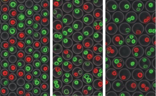 Three iterations, each of increasing well diameter. The cells are undergoing a live/dead assay. This is a rough example, but such an assay if done in an organized manner, is a very practical application of cell isolation arrays being used to check for properties such as drug toxicity.
 |
|
 |
Above: Professor Folch provides a rough model of the device's governing principle. Shear stresses, such as the jiggling of the waffle (device), force the berries (cells) into the wells. |
Scaled up: The device is fabricated to include over 12,000 microwells for large-scale analysis. Again, the live-dead assay as applied as a model, where green = live and red = dead. |
| Hydrodynamic Cell Isolation Microarray by BioPOETS (PI: Professor Luke Lee) |
In an attempt to overcome some of the problems associated with the static device such as the Folch array, BioPOETS developed an array of U-shaped weirs. The cell suspension is perfused into the device and the cells themselves are caught in the weirs. The flow of fluid mechanically locks the cells in place. Fluids can be quickly changed if needed. This overcomes the primary limitation in the static devices: in a device such as the Folch array, stagnant fluids can leech into the device’s walls, creating a variable across microenvironments, a phenomenon eliminated by the constant perfusion found here. However, this is a double-edged sword, as it forces a certain uniformity onto the microenvironment that might disguise a biologically-relevant phenomenon. For example, if a cell in the array secretes an abnormally large amount of a certain biomolecule, the perfusion might conceal this from the observer by sweeping the excess towards the exit port, whereas it would appear clearly in the static array. An example of this device in action is detailed later. |
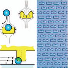 This is a basic schematic of the weir design. They are U-shaped to mechanically collect cells; the perfusion presses them into the wall. The walls do not extend to the bottom of the device, thus allowing for continued perfusion against the cell.
 |
Excessively Ambitious Techniques for Isolating Cells
Realistically, the following methods are too complicated for practical application in a clinical setting and are mentioned here simply as background for the motivation behind the development of the more practical microfluidic chips shown above.
- Protein-coated surfaces: The chip surface is patterned with “sticky” patches of ECM, functional groups, etc.
- Optical tweezing: Lasers are used to position the cells. A difficulty lies in how to minimize the number of lasers uses, as well as the energy transfer onto the cells.
- Dielectrophoresis: Electromotive force is used to trap cells in potential wells.
|
|