Haptic perception (the capability of obtaining kinesthetic (force) and tactile information) plays a very important role in surgery. It enables the surgeon to feel organic tissue hardness, measure tissue properties, evaluate anatomical structures, and allows him/her to commit appropriate force control actions for safe tissue manipulation. However, in minimally invasive surgery, the surgeon’s ability of perceiving valuable haptic information through surgical instruments is severely impaired. Performing the surgery without such sensory information could lead to increase of tissue trauma and vital organic tissue damage. In order to restore the surgeon’s perceptual capability, methods of force and tactile sensing have been applied with attempts to develop instruments that can be used to detect tissue contact forces and generate haptic feedback to the surgeon.
Recently, robots in master–slave configurations such as the ZEUS Surgical System and the da Vinci Surgical System have been introduced to solve motion constraint problems in MIS. As a consequence, dexterity of tool and tissue manipulation has been considerably augmented. This achievement facilitates surgeons to carry out a variety of minimally invasive operations more effectively including complex surgical operations (that are very difficult to be conducted using minimally invasive techniques) such as coronary artery bypass and mitral valve repair. However, force and tactile information is still not available to the surgeon. The force applied to an organic tissue can only be estimated through visual feedback by observing the deformation of the tissue. Such lack of the sensing ability greatly limits effectiveness of the operations and is considered a major downside of the current robotic systems.
In order to perform the surgery effectively, the surgeon should be able to feel hardness or tension of tissues, measure the variation of their properties, and evaluate anatomical structures such as nerves, vessels, and ducts. Tumors buried under the tissue surface may not be discovered even with advanced visual devices, but it could be detected by a simple sense of touch. Restoring and enhancing capability of tactile sensation using a touch sensitive device is, therefore, very substantial to perform tissue recognition. For tissue manipulation, retraction, and dissection, kinesthetic sensation is particularly essential as to prevent the application of excessive forces. As found in several experimental studies, performing such important tasks without force feedback could result in increasing tissue trauma and the unintentional damage of healthy tissue.
Instrumentation Design and Considerations
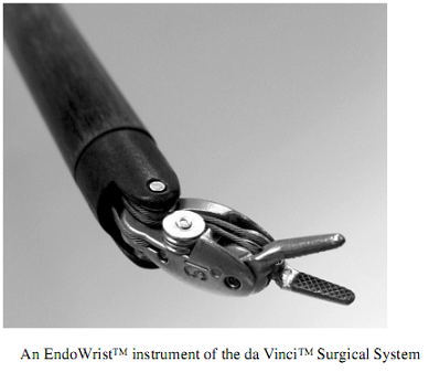
To perform surgery in a minimally invasive manner, a surgeon usually inserts straight long tools such as endoscopic or laparoscopic instruments through incisions of about 3–12 mm diameter. The motion of such instruments is considerably constrained by the fulcrum at each insertion port allowing only movement in four possible degrees of freedom (insertion, pitch, yaw, and roll). Modern laparoscopic instruments such as EndoWrist instruments of the da Vinci Surgical System have articulated joints at the distal end of its shaft near the gripper providing more degrees of dexterity to facilitate surgery (see figure below). However, because EndoWrist and other commercialized laparoscopic instruments possess no force sensing capability, their effectiveness is still limited.
To solve problems due to the lack of force sensing ability, sensing elements must be integrated with the instruments. Size and complexity of such elements depend on the degrees of freedom required for the force measurement. For a highly dexterous instrument, especially that of a robotic system, the measurement of forces and torques in all six degrees of freedom might be most desirable, though not always required. The placement of the sensing elements is also an important matter that could greatly influence the quality of force measurement. Basically, there are at least four locations where the sensing elements might be placed. The figure below shows the four possible positions to place sensing elements.
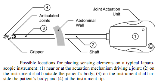
1) Located near or at the actuation mechanism driving a joint
If the surgical instrument has active joints driven by some sources of actuation, it is possible to measure forces acting at the instrument tip by way of monitoring stress of the mechanical linkages or responses of the actuators. However, because the effects of forces are transferred to the sensing area through mechanical linkages, friction, backlash, gravity, and inertia could distort the force values causing errors in the measurement.
2) Located on the instrument shaft outside the patient’s body
Because this part of the instrument needs not to pass through the instrument insertion port, there is not much constraint with respect to the size and materials sensing devices used in this case. However, a sensing device placed at this position is considerably subjected to friction and reaction forces created at the instrument insertion port. The quantity of those could be much higher than the tissue interaction forces acting at the instrument tip. Measuring the forces at this location without any means of friction compensation is thus not practical, because the sensitivity of tissue contact force measurements is reduced.
3) Located on the instrument shaft inside the patient’s body
At this location, friction and reaction forces generated at the instrument insertion port do not affect the measurement of the tissue contact forces. It is therefore considered as one of the most desirable places for locating a sensing element. However, this location encounters severe space limitations. Since the whole sensing device must pass through the insertion port, the dimension of the instrument measured at this position is usually limited to only 12 mm in diameter. While facing such restriction, inertial and actuation forces generated from the mechanics and drive assemblies such as cables actuating distal articulated joints or the gripper could also disturb the measurement of the tissue interaction forces.
4) Located at the instrument tip such as on a gripper jaw
Instruments which are equipped with a gripper offer the additional possibility of integrating force sensors in the gripper. The jaw is the place where forces acting at the surgical instrument tip can be measured most directly. Friction and other disturbance forces generated from any moving mechanisms do not affect the measurement of the tissue contact forces as much as that in the other cases. Unfortunately, the jaw is the place that exhibits most severe space limitations. Only instruments which have either a large gripper or extremely small sensing elements can be considered for this case.
Sensing Methods
1) Displacement-based Sensing
One of the simplest methods to sense forces is to detect the displacement change of an elastic element such as a linear spring. Referred to the force-displacement relationship described in a common physics law, a change in spring length indicates the magnitude of the overall force acting on it. A displacement sensor such as a potentiometer, a digital encoder, a linear variable differential transformer (LVDT), or other devices which can provide an accurate displacement measurement can be applied as a sensing element. LVDT-based force transducer is one of the well-known force sensing devices. The LVDT core is usually coupled with a linear elastic element. When a force is applied and causes the elastic element to deform, the position of the LVDT core will change allowing an analog signal to be generated in proportion to the applied force. This sensing scheme is capable of providing accurate measurements and can even resolve millinewton forces. More advanced techniques eliminate the use of the real elastic element but simulate its characteristics in a servo system. An approach to measure forces in a teleoperated force reflecting endoscopic grasper (FREG). According to the instrument design, the grasper’s jaws are driven by a flat coil actuator which is a modified hard disk head positioning device. This actuator is connected with a high-resolution position encoder and a proportional-derivative (PD) controller to form a servo control configuration. The proportional gain incorporated with an appropriate derivative gain of the controller was set such that it effectively and efficiently simulates a high mechanical stiffness characteristic, as usually required to ensure transparency in a force feedback system. Thus, the real mechanical elastic element was not used but the servo was applied to mimic its elastic behavior. Mechanical properties of grasped objects such as tissue hardness can also be felt.
2) Current-based Sensing
Another possibility to measure forces is to detect the current of electric motors actuating particular joints. If the joints are driven by servo control mechanisms, the value of torques or forces generated by the servo motors can be determined since they are usually proportional to the armature current of the motors. Based on this principle, a force exerted on the motor axis could be considered as a disturbance of the servo control system. Any efforts of the controller that attempt to increase the motor current to produce sufficient force for balancing disturbance effects can be interpreted as a magnitude of the force being measured.
3) Pressure-based Sensing
An alternative way to develop a force sensing device is to make use of pneumatic equipment. Recently, four degree-of-freedom pneumatic-driven forceps that posses force sensing capability have been developed. The forceps consists of four joints, which are driven by wire rope power transmission mechanisms actuated by servo pneumatic actuators. In this system, the delicate force sensing capability was constituted by introducing a disturbance observer to the pneumatic servo system. The information which is necessary for the estimation of the forceps contact forces such as the differential pressure of the pneumatic cylinders, joint displacements, and joint velocities are supplied to a disturbance observer. Those are further processed by an internal estimation protocol. The observer makes use of a neural network to estimate possible driving forces of all joints which are then compared with the forces estimated from the measurements of the pneumatic cylinder pressures. The differences indicating the contact forces are low-pass filtered so that the actual contact forces at the forceps tip are effectively predicted. Performance tests show that the forceps has good sensing ability, being capable of determining contact force values with a resolution of as good as 0.1 N.
4) Resistive-based Sensing
In many applications, most of the force measuring devices use strain gauges as their sensing elements. To provide an accurate means of force measurement, the strain gauge is usually bonded to a flexible structure called flexure. When a force causes strain in the structure, the electrical resistance of the strain gauge will change allowing the applied force to be electrically measured. However, because the underlying principle of the strain-gauge measurement is based on the measurement of the structural deformation, there is always a tradeoff between the stiffness of the structure and the sensitivity of the measurement. In robotic systems, for instance, high stiffness characteristic of the structure is substantial for sustaining mechanical linkages, working instruments, and objects being manipulated. Unfortunately, stiff structures tend to provide low measurement sensitivity. Another phenomenon that restricts flexibility of the sensing device design is hysteresis. To prevent possible unwanted effects caused by such phenomenon, a monolithic flexure made of a single piece of metal, is usually exploited. In MIS, developing a force sensing device is even more challenging since limitations in size greatly restrict the flexibility of sensing device design. At the University of Washington, however, strain gauges were applied in a motorized endoscopic grasper (MEG) for measuring forces and tissue properties. They were placed in a partial pulley, which was used as a mechanism to drive the instrument’s jaws. The pulley does not pass through the instrument insertion port but is linked to the jaws at the instrument tip by a linear translation linkage. A brushed DC motor equipped with a digital encoder was installed to motorize all these mechanisms. Because the strain gauges, motor, and other electric components always lie outside the abdominal cavity, they need not to be sterilized. Only the interchangeable laparoscopic instrument shaft is needed to be dismounted and autoclaved afterwards. The development of force sensing instruments based on strain gauge technology has also been conducted at John Hopkins University. Recently, a two degree-of-freedom force sensing sleeve that can be integrated with a variety of 5 mm laparoscopic instruments has been developed.
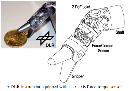
Strain gauge sensing also provides solutions to even more complex force measurements. At the German Aerospace Center (DLR), a distal force-torque sensor for laparoscopic instruments (see figure below) has been developed. The sensor makes use of a hexapod structure known as the Stewart Platform to locate six strain gauges for measuring forces and torques along all of its six measurement axes. By taking advantage of such a special hexapod structure fabricated from AlCuMg alloy, the sensor has achieved good measurement sensitivity with a very satisfactory structural stiffness characteristic. It can measure forces with a resolution of 0.25 N in the axial direction and 0.05 N in the radial direction. The measurement ranges could be as high as +/-20 N and +/-200 N-mm for the force and torque measurements, respectively. The whole device has a diameter of 10 mm, which is acceptable for MIS.
Recent advances in micro-electromechanical systems (MEMS) have also contributed to the development of miniaturized force sensing instruments such as sensor integrated forceps, and smart cutting tools. In the industrial sector, Verimetra, Inc., for instance, is one of the active biomedical device manufacturers that have conducted intensive research on applying a new microfabrication technique for creating smart surgical devices. Robotic microforceps and surgical sharps, with strain gauges embedded in their surfaces, were successfully developed on extremely small scale. This demonstrates the great potential of microfabrication technology in the medical area, in particular, for miniaturized MIS-capable smart devices.
5) Capacitive-based Sensing
Among several sensing principles, capacitive-based sensing is known as one of the most powerful means for detecting extremely small deflections of structures. For many applications which require better performance than strain gauge sensing can provide, capacitive sensing schemes represent an alternative, offering very good sensitivity to very small deflections without direct temperature dependence. Based on the capacitance measurement principle, researchers at Harvard University have developed a remote palpation system, which was intentionally designed for helping the surgeons to search for hidden arteries and tumors buried inside tissues during MIS procedures. The sensing component of the system is a capacitive tactile array sensor made of two cross layers of copper strips. All of these are separated by thin strips of silicone rubber. When a force is exerted above the crossed strip structure, the distances between the copper strips will decrease causing changes of the capacitance values. The capacitance changes measured at all crossing points were then used to determine a spatially distributed set of forces with a possible resolution of as good as 0.001 N over a measurement range of 2 N. The entire tactile array sensor was placed on a handheld laparoscopic palpation instrument allowing the surgeon to press the sensor against the surface areas of interest. With specially designed electronics and a computer-based signal processing system, various forms of delicate palpation information such as variations in pulsatile pressure of arteries, stiffness, and texture of soft tissues could be read out and conveyed to the surgeon by either a visual or an intuitive tactile display.
6) Piezoelectric-based Sensing
Piezoelectric materials have also been considered as potentially effective sensing elements in tactile sensors. If well fabricated, they are able to provide several advantages over other types of sensing devices. For instance, they can sensitively generate voltages when their structures are deformed due to compression. Although an extremely small deformation is caused by a small punching force, a large output voltage can be generated.
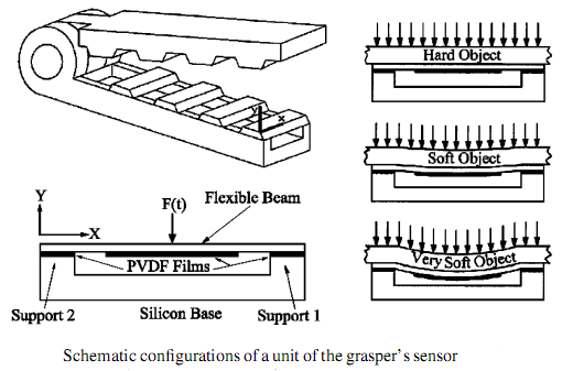
The capability to produce voltages distinguishes piezoelectric sensors from most other sensors. Since no electrical power is needed to be supplied to the sensing elements, their operations are considered very reliable and the application range is greater than with other sensors. One of the many piezoelectric materials is the polymer, polyvinylidene fluoride. Referred to as either PVDF or PVF2, it is one of the most well-known materials used for constructing thin sheet tactile sensors. For an application in MIS, such material was applied in the development of a micromachined tactile sensor that can be equipped with a jaw of endoscopic graspers. The sensing element, a PVDF film, was attached with a number of patterned aluminum electrodes. They all were placed between a rigid tooth-like silicon structure and a flat Plexiglass substrate plate. For a prototype sensor, four electrodes were placed right under the teeth of the silicon structure. When a force causes stress in the PVDF film, polarization charges which produce voltage signals are generated. The magnitude, position, and distribution of the applied force can then be determined by measuring the amplitude of the output voltages at all electrodes and comparing such quantities among them. This sensor exhibits very high sensitivity and good linearity. High signal-to-noise ratio over a measurement range of 2 N was also achieved with this design. Subsequent research on the PVDF-based tactile sensor led to a novel sensing structure design that can simultaneously measure the magnitude of the applied force, the location of the force, its distribution, and additionally the tissue softness. A design of an MIS grasper has been proposed, where each sensor unit comprises three PVDF films. One is attached to a flexible beam and two are located on both of its end supports (see figure below). The force applied on the beam can be measured by the PVDF films at its supports while the softness of an object being grasped can be quantified from the beam deflection detected by the PVDF film attached to the beam.
Although many piezoelectric-based sensors offer a variety of advantages, it is important to note that piezoelectric materials are inherently subject to charge leakages which cause deteriorations of voltages or drifts in the presence of static forces. This characteristic makes piezoelectric sensors only sensitive to time-varying force quantities. For applications that require detection of static forces, piezoelectric sensors would not provide true measurements. Another drawback is concerning the pyro-electric property of piezoelectric materials. Tactile sensors made of piezoelectric elements could be very sensitive to changes in temperature. Without an effective means of protection or compensation, the ability to obtain accurate tactile information from this type of sensor could be limited.
7) Vibration-based Sensing
Instead of relying on the detection of forces using passive force sensing elements, some tactile sensors are capable of obtaining tactile information through dynamic responses. This refers to the development of the so-called miniaturized vibrotactile sensors that can be used to measure the dynamic mechanical properties of soft tissues including dynamical stiffness during MIS. At Fraunhofer Institute for Biomedical Engineering in Germany, a vibrotactile sensor prototype was designed, comprising an alternate current (AC) excitation coil which generates an oscillatory magnetic field to induce vibration on a permanent magnet. The magnet, which is attached with an elastomer membrane located at the tip of the sensor head, can vibrate within a range of 100–800 Hz. The amplitude, phase, and frequency of the vibration are accurately measured by using an eddy current sensing scheme. This involves the use of additional components including a conducting disc placed on the permanent magnet and a measurement coil located nearby. When the vibration is activated, the conducting disc, magnet, and elastomer membrane will start to oscillate at a resonance frequency. The eddy current induced in the conducting disc causes cyclic changes of the electrical impedance of the measurement coil allowing the amplitude, phase, and frequency of the oscillatory movement to be measured. The resonance frequency as well as the phase and amplitude will be changed when the sensor comes into contact with a sample of soft tissue, due to its viscoelastic property dampening the harmonic oscillation. Information concerning mechanical properties of the tissue can then be derived from such changes including the tissue stiffness, since the resonance frequency of the sensor in contact with the tissue tends to increase with increasing tissue stiffness.
8) Optical-based Sensing
Applying an optical sensing scheme is an alternative way to measure forces and transfer force information. Instead of using electrical wires to carry electrical signals, fiber optic cables are used as a medium to carry force information from a sensing region to optoelectronic equipment. A sensor which applies an optical sensing scheme using optical fibers is also known as an optical fiber sensor. The fundamental components of an optical fiber force sensor are a light source, a transduction element (also known as a modulator), and an optical detector. The light source generates light that travels to the transduction element through a light transmitting optical fiber. The transduction element modulates the light in proportion to the value of the force being measured. The modulated light then travels through a receiving optical fiber to the optical detector. After the light reaches the detector, it is converted into an electrical signal and further processed by electronic equipment. Generally, the optical detector consists of a photodiode and signal conditioning circuitry that can amplify the electrical signal produced by the photodiode. The light source could be a light emitting diode (LED), a laser, or even a halogen lamp. Most often, LEDs are utilized since they are reliable, widely available, and inexpensive. In cases where high optical power output is required, lasers or halogen lamps are employed.
The sensing methods that are usually applied to fiber optic sensors can be classified in two major categories known as extrinsic and intrinsic sensing. In an extrinsic sensor, the optical fiber serves as a transmission medium to deliver a light signal from the light source to the transduction element and from the transduction element to the detector. Differently, in an intrinsic sensor, the light modulation occurs inside the fiber itself. A measured variable such as force or pressure deforms the fiber causing its conductivity to change and, therefore, the light traveling in it is modulated.
In an intensity-modulated sensor, the intensity of the light beam traveling through an optical fiber is modified by the effect of a measured variable in the transduction region. Its value can be determined in proportion to the light intensity detected at an optical detector. This sensing mechanism makes use of a reflector to deliver the light transmitted from the transmitting optical fiber to the optical detector. The intensity of the light can vary due to changes of the distance between the reflector and the fiber tips. As the distance decreases, increasing amounts of light proportional to distance are captured by the receiving fiber. In practice, a coupler is often used to couple the transmitting and the receiving light into a single fiber. A portion of the light transmitted through the transmitting fiber can also be provided as a reference for the optoelectronic signal processing (left figure below). Apart from this benefit, the use of a coupler also offers a good configuration for the light intensity measurement. Since only a single fiber is wired to the sensing element, signal distortion due to misalignment between the fibers is eliminated.
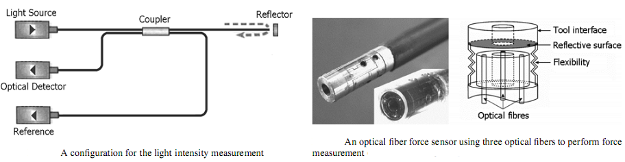
At Leuven University, researchers have utilized this configuration in a 5 mm diameter force sensor for minimally invasive robotic surgery (MIRS) applications. Three optical fiber sensors were employed to measure deformations of a flexible titanium alloy (Ti6A14V) structure mounted on a surgical instrument shaft (right figure above).
Although optical fibers have great potential for sensing instrument development, there are limitations in utilizing such materials. Particularly in intensity-modulated sensors where the measurement principle relies on the measurement of the light intensity, the measurement accuracy could be degraded if the light signal is altered outside the transduction region such as outside the fiber cables and near their connections due to bending and misalignments. Thus, means of prevention or compensation such as using a reference fiber have to be incorporated. Also, many types of optical fibers are not as flexible as electric wires; they are easily damaged and usually require precise interfaces with other system components. Small fiber bending can cause signal attenuation and fluctuation that must be compensated for, while large bending can lead to damage in the fiber core.