Microfluidic Dynamics:
The attraction to utilizing microfluidics stems from its potential to improve efficiency and therefore significantly minimize costs. There are two main factors of microfluidics which yield the above advantages. The first is simply that microfluidics only uses microliters or nanoliters of solutions which significantly reduces material’s cost. The second factor is the advantages that can be exploited from the physical properties of fluids at these small volumes. There are two dimensionless numbers, Reynold’s number and Peclet number, which characterize fluid flow and how molecules within that fluid act, respectively. The Reynold’s number is able to classify the fluid dynamics into either laminar or turbulent, which are depicted in the figure below. Turbulent flow is what most people are familiar with; it is described as a fluid which chaotically flows with no distinct streamlines. Laminar flow is that of a fluid which has distinct streamlines which are all parallel to the direction the fluid is moving.
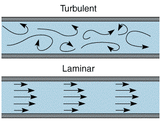
The equation to calculate the Reynold’s number is Re = ρvl/n where, ρ is the density of the fluid, ν is the velocity of the fluid, l is the characteristic length of the channel, and n is the viscosity of the fluid. For large Reynold’s numbers, typically greater than 1000, fluid flow is classified as turbulent. In the case of microfluidic devices, since the characteristic length is so small, Reynold’s numbers are mostly always less than 1 which I falls into the category of laminar flow. The advantage of laminar flow is that due to the steady streamlines, fluids can be manipulated very precisely, and molecules within the fluid can be controlled easily to form predictable gradients.
The calculated Peclet number determines whether diffusion or convection is the dominate means of mass transport by values larger than 1 and less than 1, respectively. The values of the Peclet number can be calculated by the equation Pe = vl/D where ν is the velocity of the fluid, l is the characteristic length of the fluid, and D is the diffusion coefficient. A typical example of these two processes is mixing of sugar in a cup of coffee. If one uses a spoon to mix the sugar then the means of transport of the sugar in the coffee is convection. This is because the spoon is causing a bulk flow of the fluid which in turn causes the sugar molecules to evenly disperse. However, if one simply puts the sugar in the coffee without stirring, the sugar molecules will slowly mix with the coffee by the process of diffusion. Diffusion is a process where molecules automatically have a net flux down a concentration gradient. Although convection occurs much faster than diffusion, for very small volumes, as such in microfluidic devices, the more efficient means of transport occurs by diffusion. This property allows for very exact and reproducible gradient profiles to be generated in a variety of ways. The exploitation of these properties has led to a myriad of devices ranging from very basic T-channels to sophisticated integrated circuits. The application of these devices has been for both cell-based assays and diagnostic testing.
Device Fabrication:
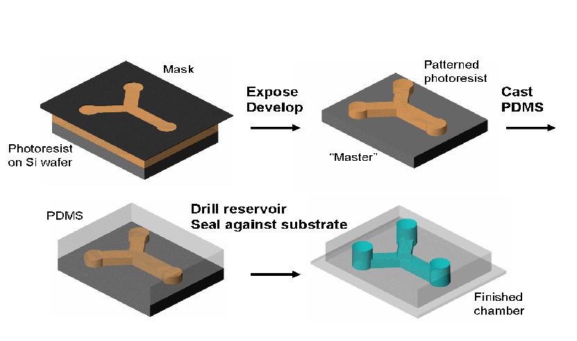
Most microfluidic devices are made by a process called soft lithography. Soft lithography utilizes an elastomer called polydimethylsiloxane (PDMS) to make a negative mold of a master mold which is made by photolithography.
The overall scheme to making a microfluidic device is that a master mold of a desired pattern is made (photolithography) and then an elastomer named PDMS is baked on that mold to form the negative of that master mold (soft-lithography). The elastomer is cut out from that master mold and sealed against a glass slide forming microchannels. The elastomer can then be repoured onto the master mold and the process can repeat as long as the master mold is not damaged.
The master mold which the cured PDMS conforms to is made by photolithography. This procedure makes extruded structures on a flat silicone wafer. The structures are created by pouring a photoresist onto the silicone wafer and then spinning the wafer to get a uniform layer of the photoresist at a specific thickness. The thickness is determined by then angular velocity which the spin-caster rotates at; the faster it spins the thinner the photoresist will be. The photoresist is comprised of three components: epoxy resin, solvent, and photo-acid generator. The photoresist covered wafer is then baked to evaporate the solvent so that it becomes solid. A transparency mask is then used to pattern the photoresist. The pattern allows UV light to hit specific regions which produces a strong acid (HSbF 6) that in turns causes the epoxy resin to crosslink into a ladder structure. This allows the epoxy resin which was crosslinked to not be washed away when put in a developer.
The elastomer material is made from a material called polydimethylsiloxane (PDMS). The advantages of this material are that it is both transparent and allows the permeation of oxygen. The transparency of PDMS allows the visualization of fluids or cells in the device while the capability of oxygen permeation negates the buildup of bubbles. The procedure to make a PDMS mold is coined soft-lithography. Soft-lithography is using PDMS to form a negative mold from a master mold. PDMS is comprised of two basic components, an elastomer base and curing agent which are both liquid. The elastomer base contains siloxane oligomers and siloxane cross-linkers. The curing agent contains a platinum based catalyst. So when these two components are mixed together they crosslink and form an elastomer that takes the shape of the mold which it is on. The cross-linking occurs by an organomettalic crosslinking reaction where the platinum-based catalyst adds a SiH bond from the siloxane cross-linker across the vinyl groups of the siloxane oligomers. Since for every siloxane cross-linker there are multiple reaction sites, a 3 dimensional structure is formed.