Terahertz (THz) Imaging Setup
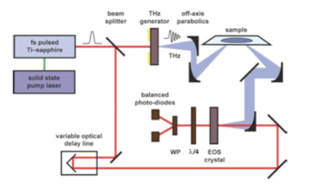
A schematic of a typical time-domain spectroscopic THz imaging system is depicted below:
Ultra-short visible/near-IR pulses of ~10-200fs and wavelengths of ~780nm are aimed at a semiconductor THz generator. The semiconductor converts the incident pulses into THz pulses. The emitted THz pulses typically emerge on the far side of the semiconductor and are subsequently reflected onto off-axis parabolic mirrors directed towards the object being imaged. The signal is then stepped across the beam to be used for building up a two-dimensional image.
The THz signal is focused and collected on the electro-optical sampling (EOS) detection crystal (typicall ZnTe [zinc telluride]). The THz field induces an instantaneous birefringence in the electro-optical medium and is measured using a quarter waveplate (λ/4), Wollaston polarization (WP) splitting prism, and two balanced photodiodes.
The following figure shows a typical signal acquired using THz imaging:
The signal measured is a function of the time-delay between the arrival of the THz beam and probe pulses at the EOS crystal. Thusly, the THz pulse in the time-domain can be obtained (left graph) and the Fourier transform gives the frequency spectrum of the THz signal (right graph).

--Links--
Applications
--External Links--
Copyright ⓒ 2009. Owen Yang. All Rights Reserved.
University of California, Irvine - Irvine 92697