Wavefront-guided LASIK utilizes the preoperative wavefront to measure the refractive error and aberrations of the eye in order to calculate the ablation profile for the LASIK procedure. In theory, wavefront-guided LASIK may produce better refractive outcomes by correcting the ocular aberrations that affect the visual acuity for all pupil diameters. Wavefront-guided or customized LASIK assumes that the aberrations of the eye can be reduced by reshaping the cornea. In normal eyes, the aberrations in the lens and the cornea are the same magnitude and balance each other, which is the basis for the assumption. Wavefront-guided LASIK assumes that the aberrations in the lens and posterior surface of the cornea do not change after surgery, since they are unaltered.
The spherical aberration contributions of each surface can be modeled in terms of ray height at the anterior corneal surface, h1,
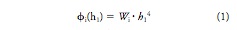
where i is the surface number and Wi is an aberration coefficient.
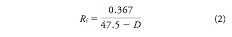
In order to correct defocus caused by myopia (D in diopters), the radius of curvature (Rf) of the postoperative cornea needs to be reduced by removing stromal tissue. To calculate postoperative Rf (meters) the equation is given below that relates D and the cornea refractive index difference between air and tissue (0.367 for this model but normally is 0.376).
The spherical aberration caused by the anterior corneal surface is given by
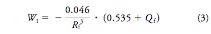
where Qf is the postoperative corneal asphericity factor. This factor can be defined in relation to the aberration coefficients of the posterior corneal surface (W2), anterior lens surface (W3), and posterior lens surface (W4),
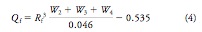
Assuming a preoperative corneal curvature of Ri and asphericity Qi, the aspheric ablation algorithm for creating a postoperative cornea of Rf curvature and Qf asphericity is given by the following equation,
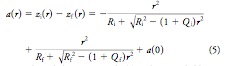
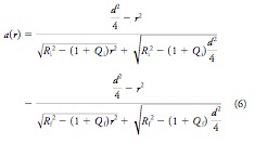
where r is the radial position and a(0) is the ablation depth at the center of the pattern. Assuming the diameter of the ablation zone (d) and that the ablation depth is zero at r = d, the equation above can be rewritten.
The figures below graph the relation between Qf and diopter correction (fig. 1) and central ablation depth a(0) and diopter correction (fig. 2).
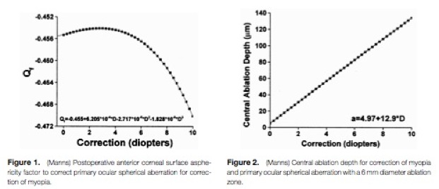
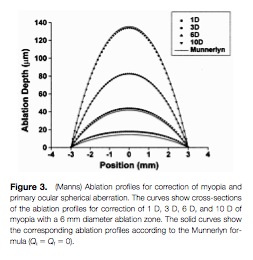
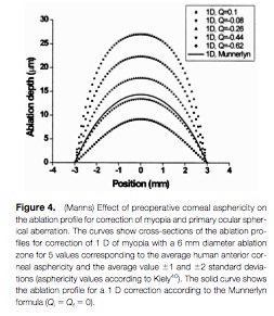
Figure 3 graphs the ablation depth for depending on radial position for the aspheric ablation equation above (assuming Qi = Qf = 0) in comparison to Munnerlyn’s equation (solid lines). This shows relative agreement for high diopter correction with increasing disparity with lower diopter values. Where as figure 4 graphs the influence of corneal asphericity on the ablation profiles.