Mechanical Valves
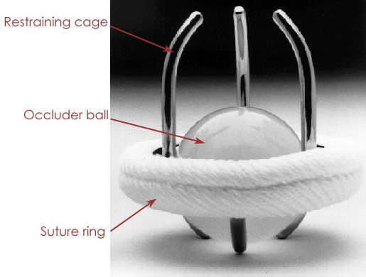
| The first replacement heart valves were constructed of synthetic materials, and are known as "mechanical" valves. This first design dates to the 1950's and is known as the “ball in cage” design. An occluder ball functions as the valve while housed in a restraining cage. The assembly is attached using a sewing ring at the base of the cage. The ball is usually made of silicon rubber, while the material used for the cage evolved from acrylic to stainless steel and finally to a cobalt-chromium alloy. Use of these materials made ball in cage valves remarkably durable. However, the relatively simple design did not exactly mimic the function of the native valve. This is because the position of the ball when the valve was in the open position disrupted the blood flow (see figure 5). | ||
Figure
5: Left: The ball-in-cage prosthetic heart valve design. The
occluder ball replaced the leaflets of the native valve as the method
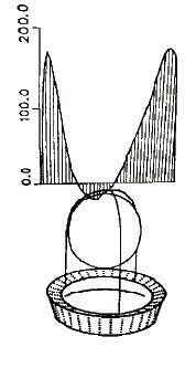
for regulating directional flow. Right: The primary drawback to
this design is a flow profile (graph denotes flow velocity) that is
disrupted towards the center due to the presence of the ball.
|
||
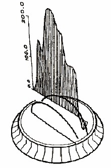
| Thus, a new design was needed. During the 1960’s, designs using leaflets
were developed (see figure 6). These leaflets were
comprised of small panels that tilted to open and close the valve. Initial designs incorporated a single leaflet
made of pyrolytic carbon-coated graphite with a centralized pivot point. The low profile of the leaflet increased the
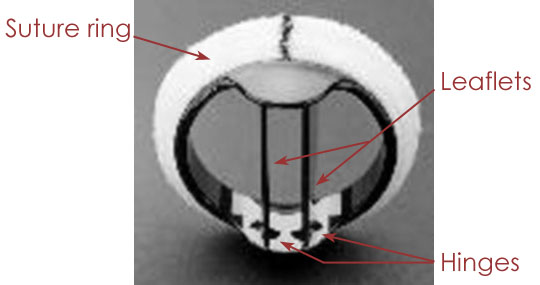
laminar flow when compared with a ball in cage valve. The current design, dating to 1979 (see figure 7), uses two
leaflets. Each is shorter than the
single leaflet design, which allows them to open completely, parallel to the
bulk flow of blood. This creates less
turbulence, and this design closely replicates the parabolic flow profile around a native heart
valve. |
||
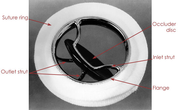
Figure
6: Left: Single leaflet mechanical valve design. Right: Velocity
(cm/s) as a function of position through the valve. Although
there is still obstruction at the center of the flow profile, this
volume is reduced compared to the ball in cage model.
|
||
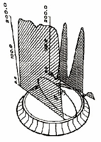
Figure
7: Left: Bileaflet design is more symmetric in nature. Right:
Velocity profile is biased towards the center, as also observed in
native heart valves.
|
||
| The primary drawback for mechanical heart valves is the
biocompatibility of the materials used.
Blood clotting and thrombus formation which would compromise the opening
and closing of the leaflets are common with mechanical valves, and as a result,
patients using these devices are usually put on anti-coagulant drugs. These drugs essentially turn all patients
into hemophiliacs. They can also cause
birth defects and as a result, mechanical heart valves are not suitable for
women who want to have children. Despite these drawbacks, mechanical heart valves remain a viable option due to their extreme durability. |
Page design and content by Vincent Nguyen-Hoai