Circuit Considerations
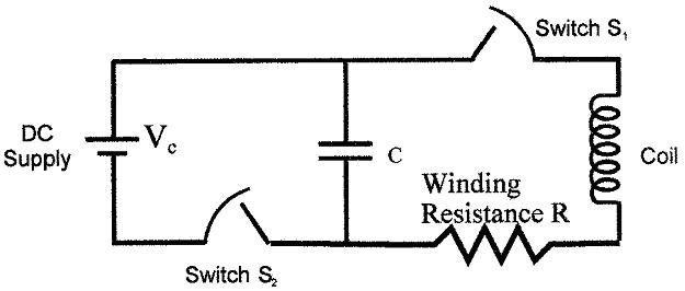
Electromagnetic stimulation devices in general are based on a capacitor driving current into the inductance of the stimulator core. A full circuit and a simplified circuit are presented in Figure 3.
Figure 3
(Full circuit)

(Simplified circuit)

The dc charged capacitor is allowed to resonate a complete cycle, and the core head is where inductance is generated. In a situation without winding resistance, the capacitive energy ![]() would shift to inductive energy
would shift to inductive energy ![]() , and reverse back to the capacitor. The period of time required for a full wavelength can be expressed by
, and reverse back to the capacitor. The period of time required for a full wavelength can be expressed by ![]() .
.
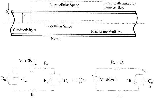
The inductor core generates a magnetic flux that passes into the biological tissue (i.e. the cortex, in the case of TMS) and induces a voltage through the tissue linked by the flux. Only a fraction of that flux will connect a circuit consisting of the intracellular and extracellular space of a nerve through the membrane wall because the induced voltage is only a fraction of the flux linking the iron core winding. The circuit of the nerve targeted by the magnetic stimulator is shown below in Figure 4.
Figure 4

During the resting state, the cell membrane is low in permeability (i.e. mobility) to ion flow (mainly Na+). The following model focuses on a subthreshold state over a long nerve length, where capacitance of the membrane wall is expressed in terms of permittivity ε for a per unit axial length ![]() , radius r, and thickness ∆.
, radius r, and thickness ∆.
![]()
Membrane resistance Rm is expressed in terms of membrane thickness and membrane wall conductance, σm.
![]()
And intracellular resistance, Ri, per unit length can be written in terms of intracellular conductivity, σi, and is significantly greater than the extracellular resistance, which is very small as a result of the extracellular space being very large.
![]()
Kent Davey and Epstein C.M.. Magnetic Stimulation Coil and Circuit Design. IEEE Transactions On Biomedical Engineering, Vol. 47, No. 11, November 2000