1. Design Challenge - Microscale
 |
 |
The graphs
above
demonstrate some of the design limitations of microsensor technology.
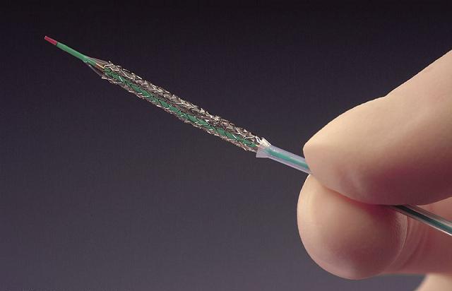
Figure on
the left shows a common intravascular stent implantation procedure for
higher
severity stenotic lesions. The metal stent surrounds the deflated
balloon
catheter (green) which, in turn, sits on top of the guide wire (red).
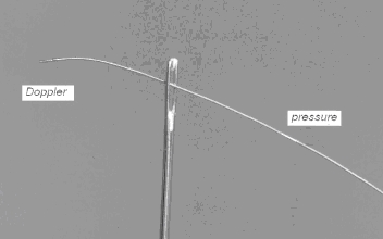
In order
to confirm re-establishment of blood flow past the lesion site,
pressure, flow
and temperature sensors would need to fit inside a 0.36 mm diameter
wire shown
on the right. This constitutes a significant design challenge and one
that has
just recently been overcome by new sensor fabrication protocols
discussed below.
 |
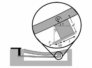 |
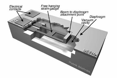
The figures
above
show a blow up view of an early microsensor based on a deflectable
polysilicon
diaphragm and a free-hanging polysilicon piezoresistor that changes
resistance
in response to torque-induced strain (right). The electrical bonding
pads
behind the piezoresistor attachment point send current in order to
monitor the
strain induced changes in resistance and feedback the signal along the
length
of the wire to an external source. The width and height of the chip
overall are
less than 0.2 mm which allows the chip to be secured to the 0.36 mm
diameter
guide wire.
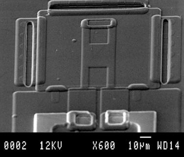
This shows
an SEM
micrograph of the chip that is integrated into the flexible guide wire
mesh
design.
